The Latest Buzz
Hardware Update #2

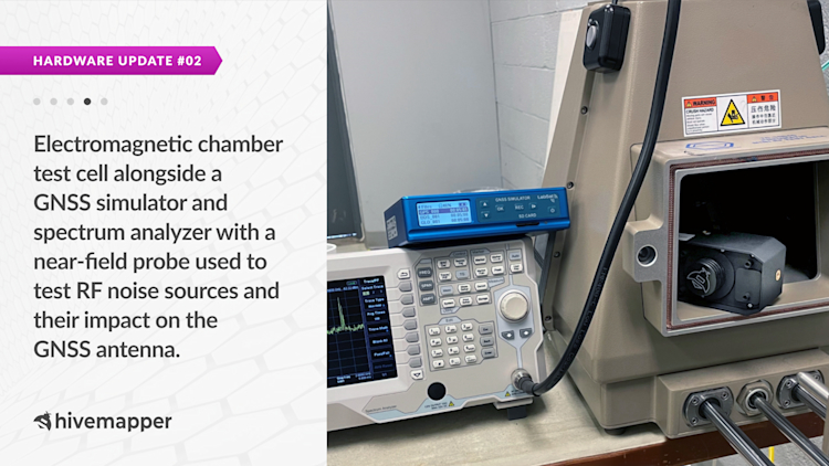
In our hardware update 2 weeks ago, we shared that during our rigorous testing and hardware validation process we discovered a hardware issue that was causing interference with our GNSS module. We’re delighted to report today that we have identified the root causes of the GNSS antenna's poor performance and have resolved them through installation and design changes.
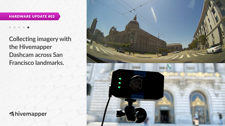
Our Head of Hardware Products, Ari Bruck, drove down San Francisco’s iconic Lombard Street and collected imagery with the Hivemapper Dashcam. Watch the video and go along for a ride.
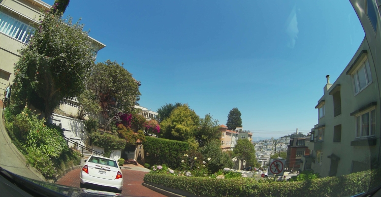
Ari Bruck, Head of Hardware Products, Hivemapper, drove down San Francisco’s iconic Lombard Street and collected imagery with the Hivemapper Dashcam. Below is an image this dashcam took.
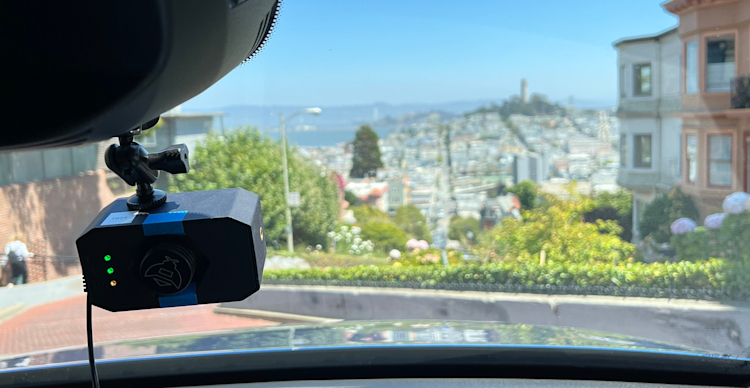
We captured this image with the Hivemapper Dashcam (pictured above) on Lombard Street in San Francisco on August 15th, 2022.
Here’s a deep dive into the issues that contributed to the GNSS antenna's poor performance in the Hivemapper Dashcam:
GNSS Antenna Installation Procedure
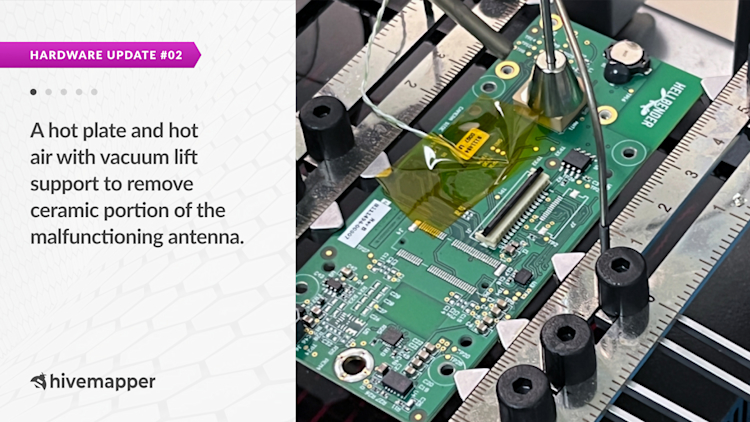
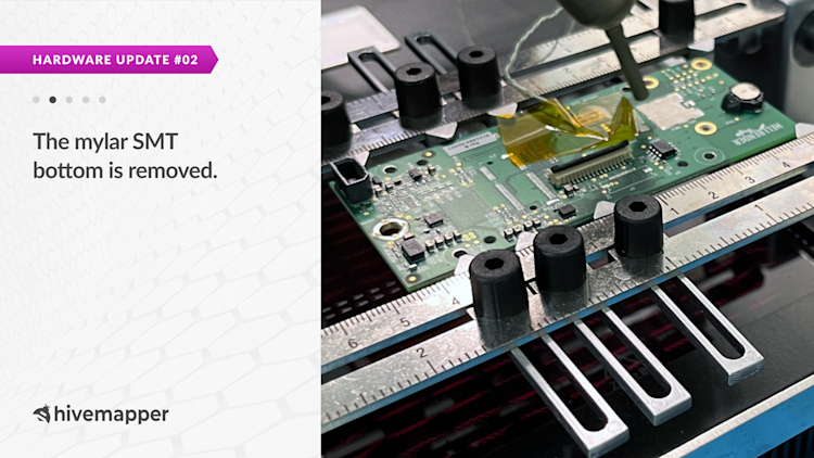
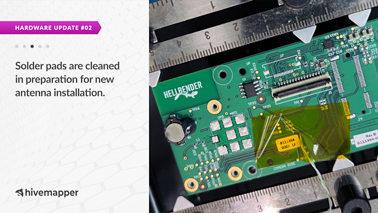
The GNSS antenna needs to be installed under certain reflow oven thermal conditions. Exceeding those conditions may damage the antenna component. To facilitate fast R&D, we used a rapid prototyping house. During our investigation, we uncovered that they didn’t follow the proper installation procedure for this antenna. The images below show the process we took to remove the damaged antennas and solder them again under the correct conditions.
Our manufacturing line will adhere to the correct parameters taking care not to damage the antenna during the reflow oven step of manufacturing.
Imager FFC (Flat Flex Cable) Connector
The imager FFC connector did not have the proper impedance matching circuit, which resulted in EMI noise emanating from the connector close to the GNSS antenna. We revised our printed circuit board (PCB) by adding the missing impedance matching circuit and moving the imager further away from the connector so that noise is reduced or eliminated.
Flat Flex Cable (FFC)
The commodity unshielded Flat Flex Cable (FFC) we originally used to connect the camera to the carrier board acted as a strong antenna emitting EMI noise nearby the GNSS antenna. We’ve updated our design to use a shorter, shielded, and grounded FFC to reduce or eliminate any noise.
Next Steps: Worldwide Testing and Hardware Validation
We’re excited to move forward with our worldwide testing and hardware validation process. We are confident that with all of these fixes in place, the Hivemapper Dashcam will perform well during this phase. Once we successfully complete this phase, we’ll be able to move to volume manufacturing and ship the Hivmeapper Dashcams to everyone who pre-ordered. We appreciate your patience and continued support and we look forward to sharing more good news with you in the near future!
Share Post
